

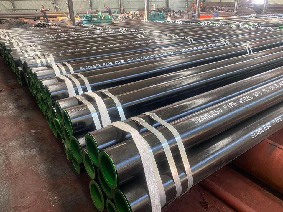
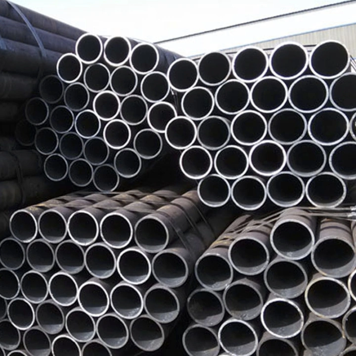
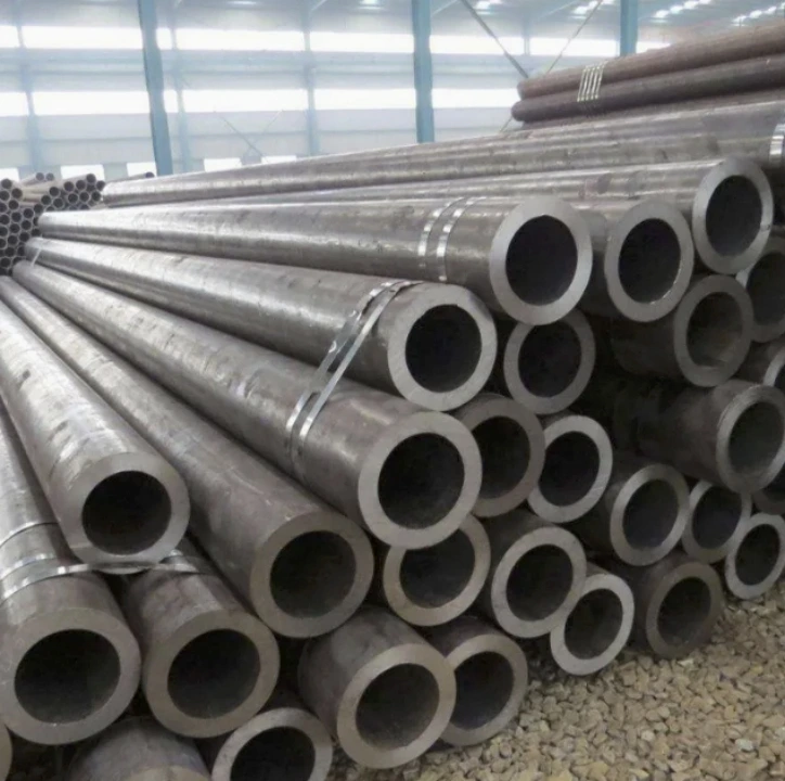
This comprehensive guide examines the technical specifications, dimensional standards, and classification systems of carbon steel pipes used in industrial applications. Understanding pipe specifications—including size designations, wall thickness schedules, material grades, and compliance standards—is critical for procurement professionals selecting appropriate piping solutions for oil & gas, construction, manufacturing, and infrastructure projects. Carbon steel pipes represent the backbone of industrial fluid transport systems, with specifications directly impacting system safety, operational efficiency, and lifecycle costs. This article provides actionable technical data for engineers, project managers, and purchasing teams navigating the complex landscape of industrial pipe procurement.
Carbon Steel Pipe Classification and Material Grades
ASTM Material Grade Standards
The American Society for Testing and Materials (ASTM) establishes the foundational material grade classifications that define carbon steel pipe performance characteristics. Three primary specifications dominate industrial applications: ASTM A53, A106, and A333, each engineered for distinct operational environments.
ASTM A53 covers black and hot-dipped galvanized welded and seamless steel pipes, primarily specified for mechanical and pressure applications. This grade contains carbon content ranging from 0.25% to 0.30%, delivering tensile strength between 48,000-60,000 psi (330-415 MPa) and minimum yield strength of 35,000 psi (240 MPa). Type F (furnace-welded) and Type E (electric resistance welded) variants serve non-critical applications, while Type S (seamless) provides enhanced reliability for pressure service.
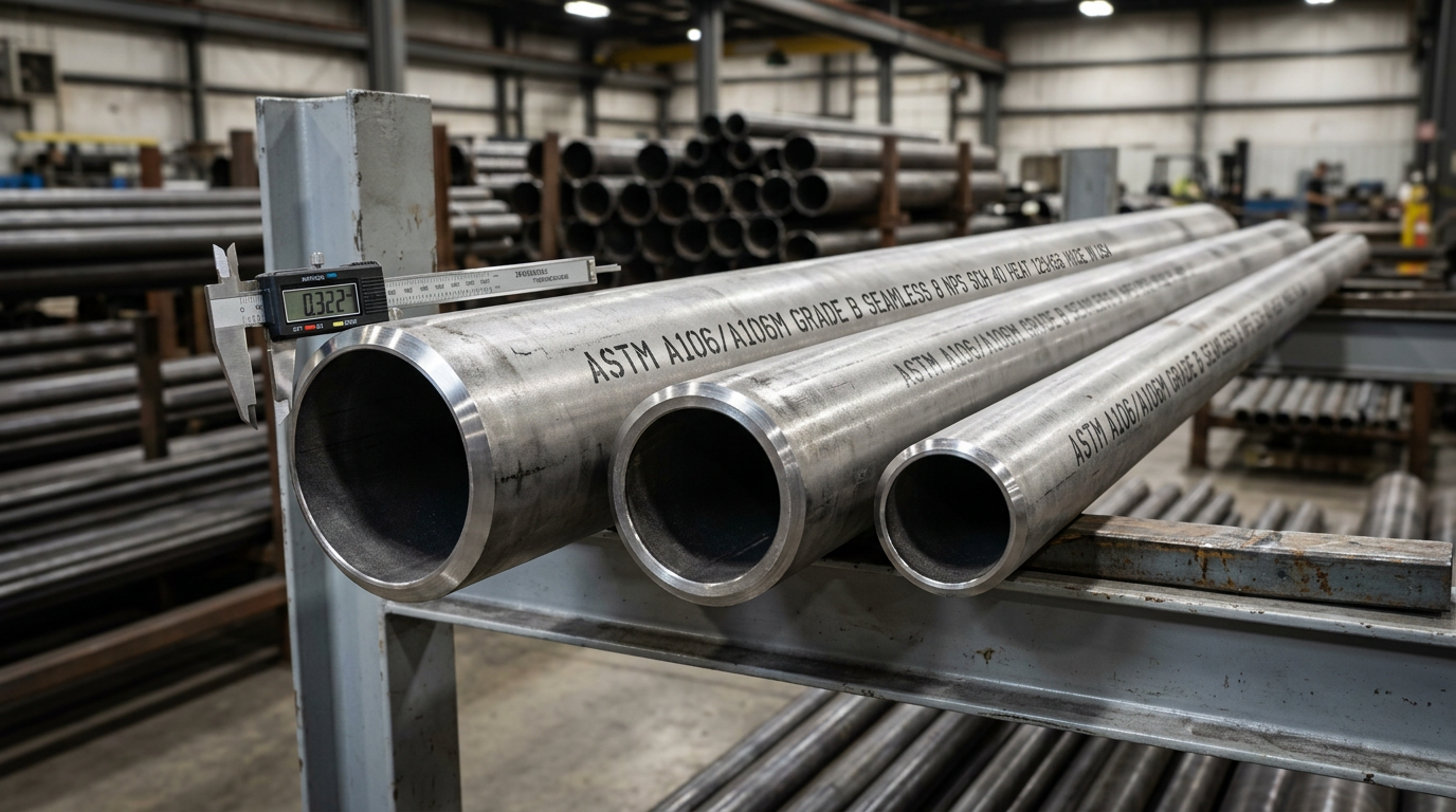
ASTM A106 represents the premium specification for seamless carbon steel pipe designed for high-temperature service. With three grades (A, B, C) differentiated by carbon content and mechanical properties, Grade B dominates industrial procurement due to optimal cost-performance balance. Grade B specifications mandate carbon content of 0.30% maximum, manganese 0.29-1.06%, phosphorus ≤0.035%, and sulfur ≤0.035%. Tensile strength requirements reach 60,000 psi minimum (415 MPa) with yield strength exceeding 35,000 psi (240 MPa). This composition ensures structural integrity at operating temperatures up to 750°F (400°C), making it indispensable for power generation, refinery processing, and steam distribution systems.
ASTM A333 addresses low-temperature service requirements, with grades specifically engineered to resist brittle fracture in cryogenic applications down to -150°F (-101°C). Grade 6 offers the broadest application range, combining impact toughness with weldability for LNG facilities, refrigeration systems, and arctic pipeline installations.
The carbon content directly influences pipe ductility, weldability, and corrosion resistance. Lower carbon percentages (0.10-0.20%) enhance formability and welding characteristics, while higher concentrations (0.25-0.30%) increase hardness and tensile strength. Procurement specifications must balance these properties against operational stress profiles and fabrication requirements.
Seamless vs. Welded Carbon Steel Pipes
Manufacturing methodology fundamentally impacts structural performance, cost positioning, and application suitability. Seamless carbon steel pipes are produced through hot-rolling solid steel billets over mandrels, creating homogeneous microstructure without longitudinal weld seams. This process delivers superior pressure resistance, uniform wall thickness distribution, and enhanced fatigue resistance under cyclic loading conditions.
Welded pipes utilize flat steel plates or coils formed into cylindrical shapes with longitudinal or spiral seams joined through electric resistance welding (ERW), submerged arc welding (SAW), or high-frequency induction welding. Modern welding technologies produce seam integrity approaching parent material strength, with heat-affected zones (HAZ) controlled through precise thermal management.
Structural integrity comparison reveals critical selection criteria. Seamless pipes eliminate the potential failure point of weld seams, providing 360-degree uniform strength distribution essential for ultra-high-pressure applications exceeding 3,000 psi (20.7 MPa). The absence of seams permits thinner wall designs for equivalent pressure ratings, reducing material costs and installation weight. However, seamless manufacturing limitations restrict availability in sizes above NPS 26 (660mm) and introduce higher per-foot costs.
Welded pipes offer economic advantages in large-diameter applications (NPS 16-80), with modern ERW processes achieving 95-98% joint efficiency ratings. Spiral-welded pipes excel in large-diameter, thin-wall configurations for low-pressure conveyance systems. Application suitability criteria prioritize seamless construction for critical services including hydraulic systems, boiler tubes, and high-pressure steam lines, while welded options serve structural applications, water distribution, and moderate-pressure industrial processes.
Dimensional Specifications and Sizing Standards
Nominal Pipe Size (NPS) and Outside Diameter (OD)
The Nominal Pipe Size system establishes standardized dimensional references enabling global component interchangeability. NPS designations represent approximate bore diameters rather than precise measurements—a critical distinction for specification accuracy. For sizes NPS 1/8 through NPS 12, the NPS number differs significantly from actual outside diameter measurements. For example, NPS 2 pipe maintains a constant OD of 2.375 inches (60.3mm) regardless of wall thickness variations.
Above NPS 14, the NPS designation directly corresponds to the outside diameter in inches, simplifying large-diameter pipe specification. This standardization enables fitting compatibility across manufacturers and facilitates system design calculations.
Metric DN (Diamètre Nominal) equivalents provide international specification alignment, with DN values representing approximate internal diameters in millimeters. Conversion follows established correlation tables: NPS 1 = DN 25, NPS 2 = DN 50, NPS 4 = DN 100, scaling proportionally through industrial size ranges.
Standard OD ranges span from NPS 1/8 (0.405″ / 10.3mm OD) for instrumentation tubing through NPS 80 (80.000″ / 2032mm OD) for major transmission pipelines. Industrial applications concentrate in the NPS 1/2 to NPS 24 range, where manufacturing economies and material availability optimize cost-performance ratios.
Wall Thickness and Schedule Ratings
Schedule numbering defines wall thickness classifications, originally developed to correlate with pressure-carrying capacity. The schedule system progresses through standardized increments: Schedule 10, 20, 30, 40, 60, 80, 100, 120, 140, and 160, with increasing numbers indicating thicker walls and higher pressure ratings.
Schedule 40 represents the most widely specified standard-weight pipe for general industrial service, balancing structural strength with material economy. Schedule 80 provides extra-strong construction for elevated pressure applications, featuring approximately 50% greater wall thickness than Schedule 40 in equivalent NPS sizes. Schedule 160 delivers double-extra-strong performance for extreme pressure and corrosive environments.
The relationship between schedule number, pressure capacity, and temperature follows the Barlow formula: P = (2St)/D, where P = internal pressure, S = allowable stress, t = wall thickness, and D = outside diameter. As operating temperature increases, allowable stress values decrease, requiring schedule upgrades to maintain equivalent pressure ratings.
Pipe Schedule Comparison Chart
| NPS | Schedule | Wall Thickness (mm) | Internal Diameter (mm) | Weight per Meter (kg) |
|---|---|---|---|---|
| 2″ | 40 | 3.91 | 52.48 | 3.64 |
| 2″ | 80 | 5.54 | 49.22 | 5.03 |
| 4″ | 40 | 6.02 | 102.26 | 14.92 |
| 4″ | 80 | 8.56 | 97.18 | 20.76 |
| 6″ | 40 | 7.11 | 154.08 | 28.26 |
| 6″ | 80 | 10.97 | 146.36 | 42.56 |
| 8″ | 40 | 8.18 | 202.74 | 43.39 |
| 8″ | 80 | 12.70 | 193.70 | 65.54 |
This tabulation demonstrates the exponential weight increase with schedule upgrades, directly impacting structural loading calculations, transportation logistics, and installation labor requirements.
Technical Performance Parameters
Pressure and Temperature Ratings
Maximum Allowable Working Pressure (MAWP) calculations integrate material grade, wall thickness, temperature exposure, and corrosion allowance factors. ASME B31.3 Process Piping Code establishes the calculation methodology: P = (2SEt)/(D – 2Yt), where S = allowable stress, E = weld joint efficiency, t = nominal wall thickness, D = outside diameter, and Y = temperature coefficient.
For ASTM A106 Grade B at ambient temperature (70°F / 21°C), allowable stress values reach 20,000 psi (138 MPa). As service temperature escalates, stress allowables decrease progressively: 17,500 psi at 400°F (204°C), 15,000 psi at 600°F (316°C), and 8,000 psi at 800°F (427°C). This temperature derating necessitates schedule upgrades or material substitutions for high-temperature services.
Pressure-temperature rating curves published by valve and fitting manufacturers correlate directly with pipe schedule selections, ensuring system component compatibility. A Schedule 40 NPS 4 A106 Grade B pipe rated for 1,440 psi at 100°F experiences rating reduction to 1,260 psi at 400°F and 960 psi at 650°F.
Corrosion allowance additions (typically 1/16″ to 1/8″) account for material loss over design life, particularly critical in sour gas service, acidic condensate systems, and seawater applications. These allowances effectively reduce pressure capacity calculations, requiring conservative schedule selection.
Mechanical Properties and Testing Requirements
Quality assurance protocols mandate rigorous testing regimens to verify specification compliance. Hydrostatic testing subjects each pipe length to internal pressure 1.5 times the rated working pressure for minimum 5-second duration, detecting manufacturing defects, weld integrity issues, and material inconsistencies. Test pressures for Schedule 40 NPS 6 pipe typically reach 2,160 psi (14.9 MPa) for standard-grade materials.
Non-destructive examination (NDE) methods include ultrasonic testing (UT) for wall thickness verification and lamination detection, radiographic testing (RT) for weld seam inspection, and magnetic particle inspection (MPI) for surface crack identification. API 5L specifications mandate 100% body UT and end-area UT for seamless pipes in critical service, with weld seam inspection requirements varying by grade and application severity.
Certification documentation packages include mill test reports (MTR) detailing chemical composition analysis, mechanical property test results, heat treatment records, and dimensional inspection data. These certificates provide traceability to original steel heats, enabling failure analysis and quality audits throughout project lifecycles.
Industry Standards and Compliance Requirements
International Specification Standards
Global procurement requires navigation of multiple specification frameworks, each reflecting regional engineering practices and regulatory philosophies. API 5L (American Petroleum Institute Specification 5L) governs line pipe for petroleum and natural gas industries, with PSL1 (Product Specification Level 1) and PSL2 classifications. PSL2 mandates enhanced quality control including Charpy V-notch impact testing, tighter chemical composition tolerances, and supplementary non-destructive examination.
EN 10217 (European Standard) addresses welded steel tubes for pressure purposes, subdividing into EN 10217-1 (non-alloy steel with specified room temperature properties) through EN 10217-7 (stainless steel). European specifications emphasize metric dimensioning and material designation systems (e.g., P235GH, P265GH) correlating to minimum yield strength values.
JIS G3454 (Japanese Industrial Standard) covers carbon steel pipes for pressure service, with STPG370 and STPG410 grades roughly equivalent to ASTM A106 Grades A and B respectively. Japanese standards incorporate unique testing protocols and dimensional tolerances reflecting domestic manufacturing capabilities.
Regional regulatory differences manifest in allowable stress values, safety factors, and inspection frequency requirements. Middle Eastern projects often mandate dual certification (ASTM + ISO), while European Union installations require CE marking and Pressure Equipment Directive (PED) compliance for Category III and IV applications.
End Connection and Coating Specifications
Pipe end preparation significantly impacts installation efficiency and joint integrity. Plain end (PE) pipes feature square-cut terminations suitable for socket welding or mechanical coupling. Beveled end (BE) configurations provide 30° or 37.5° chamfers for butt-welding applications, with land dimensions specified to ensure proper weld penetration. Threaded ends incorporate NPT (National Pipe Thread) or BSPT (British Standard Pipe Thread) profiles for mechanical connections in low-pressure services up to NPS 4.
Anti-corrosion coating systems extend service life in aggressive environments. Internal epoxy linings prevent tuberculation in potable water systems and reduce friction losses in fluid transport. External fusion-bonded epoxy (FBE) coatings provide cathodic disbondment resistance for buried pipeline applications, with typical thickness specifications of 12-16 mils (300-400 microns). Hot-dip galvanizing deposits zinc coatings (minimum 86 microns per ASTM A53) offering sacrificial protection in atmospheric exposure conditions.
Three-layer polyethylene (3LPE) and polypropylene (3LPP) systems combine FBE primers with adhesive copolymers and thermoplastic outer layers, delivering superior mechanical protection and chemical resistance for offshore and subsea installations.
Conclusion
Selecting carbon steel pipes with correct specifications requires balancing dimensional standards, material grades, pressure ratings, and compliance requirements against project-specific operational parameters and budget constraints. Procurement teams must verify ASTM/API certifications through mill test report validation, match schedule ratings to calculated system pressures with appropriate safety margins, and ensure compatibility with jurisdictional codes including ASME B31.3, B31.4, or B31.8 as applicable.
Critical specification elements include confirming seamless versus welded construction suitability, validating temperature derating factors for elevated-temperature services, and specifying appropriate end preparations and coating systems for installation methodology and environmental exposure. The economic impact of schedule selection extends beyond initial material costs to encompass transportation weight penalties, installation labor productivity, and long-term maintenance intervals.
Partnering with certified suppliers maintaining ISO 9001 quality systems and possessing relevant industry approvals (API Q1, PED Module H) guarantees specification accuracy, dimensional consistency, and metallurgical traceability. Successful carbon steel pipe procurement integrates technical specification mastery with supply chain risk management, ensuring on-time delivery of compliant materials that support safe, efficient industrial operations throughout design service life.